
Understanding ECU Controller Sensor Architecture
The excavator ECU controller relies on a network of sensors to monitor and control machine operations. These sensors provide critical data about engine performance, hydraulic pressure, and implement position. Understanding how these sensors communicate with the ECU is essential for effective troubleshooting and maintenance.
Input Sensors: The Eyes of the ECU
Input sensors feed real-time data to the ECU controller:
- Engine Speed Sensor: Monitors RPM and crankshaft position for precise fuel injection timing.
- Throttle Position Sensor: Reports operator demand to the ECU for throttle valve control.
- Hydraulic Pressure Sensors: Measure pump output pressure and load-sensing signals for flow control.
- Temperature Sensors: Monitor engine coolant, hydraulic oil, and intake air temperatures.
- Implement Position Sensors: Track boom, arm, and bucket angles for semi-automatic functions.
Output Signals: ECU Control Actions
The ECU processes input data and generates output signals to actuators:
- Injector Control: Pulse-width modulated signals to fuel injectors for precise fuel delivery.
- Solenoid Valve Commands: Control hydraulic direction, flow, and pressure through proportional valves.
- Throttle Motor Position: Electronic throttle actuation based on operator input and engine load.
- Warning Indicators: Trigger dashboard warning lights and fault codes when parameters exceed limits.
Signal Types and Voltage Ranges
Most excavator ECU sensors operate on 5V reference signals with output ranges between 0.5V and 4.5V. Some sensors use PWM (Pulse Width Modulation) or frequency-based signals. Always consult the service manual for specific voltage specifications and acceptable ranges for each sensor.
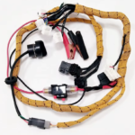
For more information on related systems, see our articles on Excavator Wiring Harness Architecture and Diagnostics and ECU Controller Diagnostic Troubleshooting Guide.